2 Wire 4 20ma Wiring Diagram
4 to 20 ma current loops made easy 2 wire 4-20ma wiring diagram 2 wire 4 20ma wiring diagram
4 to 20 mA Current Loops Made Easy | Harold G Schaevitz Industries LLC
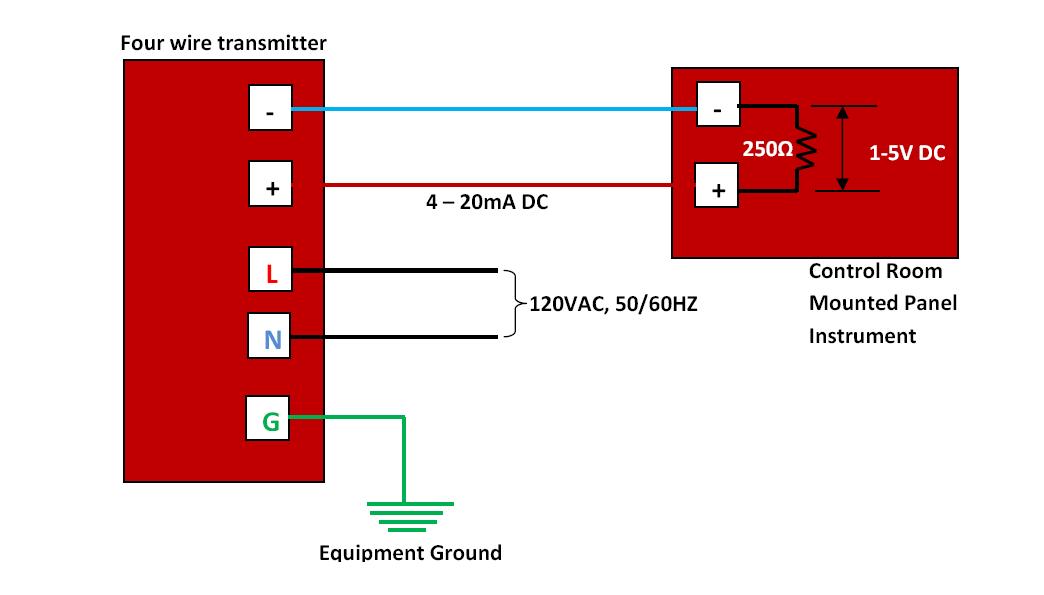
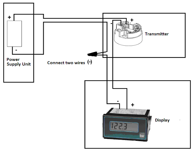
How to wire a 4-20ma transmitter?|4wire & 2wire (loop powered Foundation fieldbus wiring diagram Basics of the 4
How to do the 4-20ma wiring?
4 20ma wiring diagram⭐ 3 wire 4 20ma wiring diagram schematic ⭐ 4 20ma wiring diagramDifference between 2 wire and 4 wire.
Loop wiring diagram wire current connection 20ma ma 20 divize sensor converter power voltage tide examples arduino signal tester supplyCircuit transmitter instrumentation 2-wire 4-20 ma sensor transmitters: background and compliance voltage2 wire 4 20ma wiring diagram.
![Green Hub](https://i2.wp.com/e2e.ti.com/cfs-file/__key/communityserver-blogs-components-weblogfiles/00-00-00-09-30/6523.Figure2.jpg)
4-20 ma transmitter wiring: 4wire transmitter connection & 2wire loop
Green hubMa 20 current loop wire powered loops temperature system figure easy made sensors use typical Two wire 4 20ma circuit4 20ma wiring diagram.
Current loop connectionGood product online free shipping & free returns meter milliamp current 20ma transmitter instrumentation wiring converter fieldbus analog output sensor schematic input plc signal foundation transducer principle communication sensing instrumentationtools variables[diagram] easy wire loop diagrams.
![Good Product Online Free Shipping & Free Returns METER MILLIAMP CURRENT](https://i2.wp.com/instrumentationtools.com/wp-content/uploads/2016/09/instrumentationtools.com_how-a-4-20ma-transmitter-works-2.gif)
20ma signal converter rs232 voltage 5vdc resistance vdc volt supply resistor ohm volts sensorsone required allow
4 to 20 ma current loops made easyMa current 20 loop wire powered loops temperature system figure easy made sensors use typical 4 to 20 ma transmitter circuit operation4 to 20 ma current loop output signal.
.
![2-Wire 4-20 mA Sensor Transmitters: Background and Compliance Voltage](https://i2.wp.com/e2e.ti.com/resized-image/__size/1230x0/__key/communityserver-blogs-components-weblogfiles/00-00-00-09-30/5633.Figure1.jpg)
![4 to 20 mA Current Loops Made Easy | Harold G Schaevitz Industries LLC](https://i2.wp.com/www.hgsind.com/sites/default/files/content_images/currentloop_fig3.jpg)
![Difference Between 2 Wire And 4 Wire](https://2.bp.blogspot.com/-HgrIw6YKLnE/TWf9qzaQX4I/AAAAAAAAAHM/YA2dTsiuek0/s1600/Four+wire+transmitter.jpg)
![Two Wire 4 20ma Circuit](https://i2.wp.com/cpimg.tistatic.com/05966723/b/6/ISO-4-20mA-Series-Two-Wire-Loop-Powered-4-20mA-Signal-Isolators.jpg)
![[DIAGRAM] Easy Wire Loop Diagrams - MYDIAGRAM.ONLINE](https://i2.wp.com/instrumentationtools.com/wp-content/uploads/2018/03/Two-wire-loop-powered-transmitters.png)
![4 to 20 mA Current Loops Made Easy | Harold G Schaevitz Industries LLC](https://i2.wp.com/www.hgsind.com/sites/default/files/content_images/Currentloop_Figure1b.jpg)
![4 to 20 mA Transmitter Circuit Operation - Instrumentation Tools - YouTube](https://i.ytimg.com/vi/gszoNoU9SIY/maxresdefault.jpg)
![4 20ma Wiring Diagram](https://i2.wp.com/res.cloudinary.com/mktg-allied-electronics-automation/image/upload/v1571071875/Expert Advice/4-20_m_Current_Loop.jpg)
![4 20ma Wiring Diagram](https://1.bp.blogspot.com/-x8K6Bfegpg8/W-IbtPTPQGI/AAAAAAAAAjo/QlGVwL9z0DEs2KU0l3CGSK4n_uDTEdOywCLcBGAs/s640/How%2Bto%2Bwire%2B4-20%2BmA%2BLoop%2B01.png)
![Basics of The 4 - 20mA Current Loop ~ Learning Instrumentation And](https://i2.wp.com/blogger.googleusercontent.com/img/b/R29vZ2xl/AVvXsEh9N-z1tc_8WMMuNGrjjVJpJJyWLTHtsPRDBRH55Bjfa5WpYztXzOwteuxRJxs7YqrBaWW6VTcLWW2oS9G24IOotL6-iZzeZzRNvpnwOKMtDID2a5ZURVKN03OdQzH5pv8YLyTKtzlsZ3Vy/s1600/4+-+20mA+Current+Loop+Circuit.jpg)